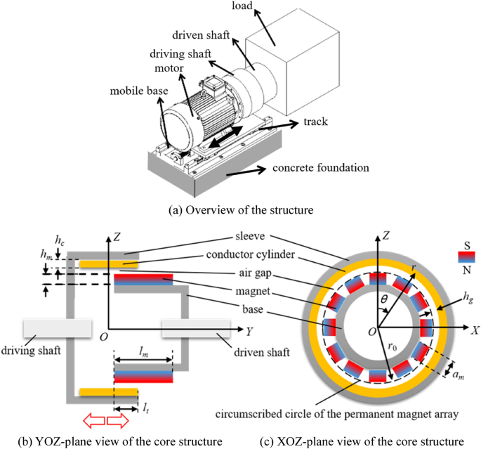
Based on former research and application20,21, the permanent magnet speed regulator, which is used to adjust the high-power cooling water pump during the steel production, is advanced to increase transmission efficiency and heat dissipation efficiency. The structure of the advanced permanent magnet speed regulator with the coordinate system is shown in Fig. 1.
As seen in Fig. 1a, this permanent magnet speed regulator includes motor, driving shaft, and driven shaft dominantly, and the motor is fixed on a mobile base with the track. The driving shaft is fixed on the motor. When the driven shaft is insert into driven shaft along with the track, meshing area between the driving and driven shafts increases as seen in Fig. 1b, enhancing the rotational resistance moment of the motor. In order to keep the rotative velocity, the motor outputs higher power. Detection, judgement, and control to the driving shaft fixed the motor are carried out by PLC.
As seen in Fig. 1b,c, 12 pieces of permanent magnet, which are used as the key component of the driving shaft, are arranged by the alternating N–S pole array on the dodecagon-type base. The copper conductor cylinder is fixed on the inner surface of the sleeve. The dodecagon-type base and the sleeve are made of steel, and also used as yoke iron to strengthen the magnetic intensity in the region between them. Thickness of the air gap hg is defined as the distance from circumscribed circle of the permanent magnet array to the inner surface of the conductor cylinder. The key sizes remarked in figure are shown in Table 1. Magnet designation used in this device is N52.
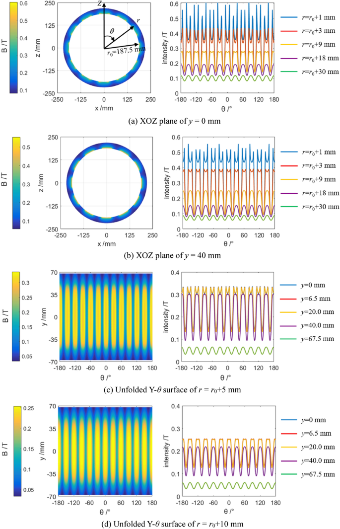
Insert depth (lt) of the driving unit, which is adjusted by mobile base, can reach to the long size of the permanent magnet in Y axis (lm). The r–θ coordinate system is also introduced into XOZ plane of the Cartesian coordinate system, reducing difficulty of the calculation in simulation. According to Ampere molecular current hypothesis and Biot–Savart law22,23, magnetic intensity induced by the permanent magnet array has been simulated, as shown in Fig. 2.
As seen in Fig. 2, a relatively higher magnetic intensity was gain due to the yoke iron. The maximal magnetic intensity could be reached to 0.25–0.3 T in the plane away of 9 mm from the magnet array.
According to Maxwell’s equations with Faraday law24,25, induced current density in the copper conductor is as
$$\boldsymbol{J} = \, \sigma \boldsymbol{v} \times \boldsymbol{B} – \sigma \partial {\boldsymbol A}/\partial t$$
(1)
$$\boldsymbol{B} = \nabla \times \boldsymbol{A}$$
(2)
where σ is the conductivity of copper; B is the vector of induced magnetic intensity; A is an introduced vector named as magnetic potential; v is the vector of relative speed between conductor cylinder and magnet array, and it can be calculated by
$$\boldsymbol{v} = \, \omega { \boldsymbol{r}} = { 2}\pi sN{\boldsymbol{r}}$$
(3)
where ω is the relative angular frequency between conductor cylinder and magnet array; s, N and r are the slip difference, input rotation velocity, and the vector of polar axis in the r–θ coordinate system.
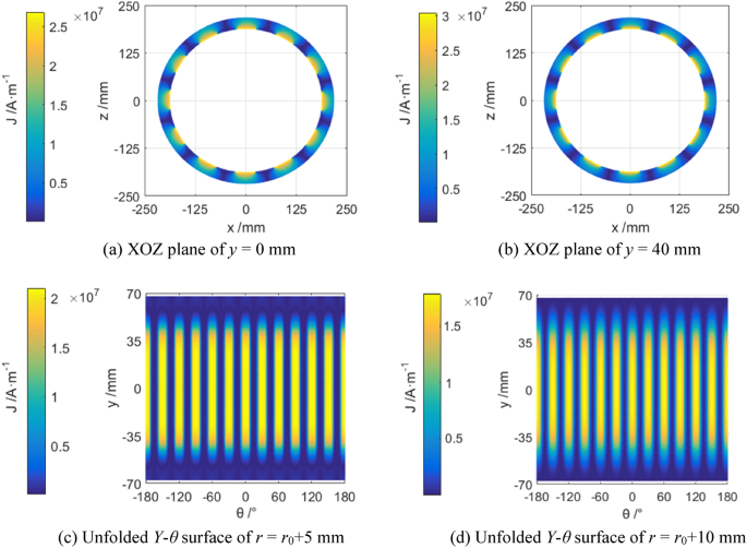
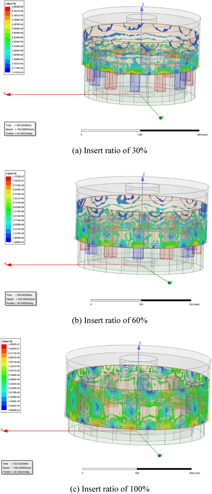
As seen in formula (3), current density J will be changed in proportional variation with the relative angular frequency ω or slip difference s. Simulated current density of the magnetic eddy induced by the relative motion between the permanent magnet array and the conductor cylinder (ω = 1 rad/s) is shown in Fig. 3, and their vector-graph are shown in Fig. 4c Insert ratio of 100% (Fig. 4).
As seen in Figs. 3 and 4, the 12 independent magnetic eddies can be observed clearly under different insert ratios of driving shaft. However, the surficial current intensity of magnetic eddy is influenced seriously by the meshing area due to insert ratio. Higher surficial current intensity of magnetic eddy means the larger magnetic resistance from the driven shaft against the driving shaft16,19. And then the latter will increase the power to keep the set rotative velocity of the motor.


