[ad_1]
Evolution of Single-Element Antenna
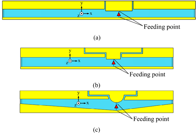
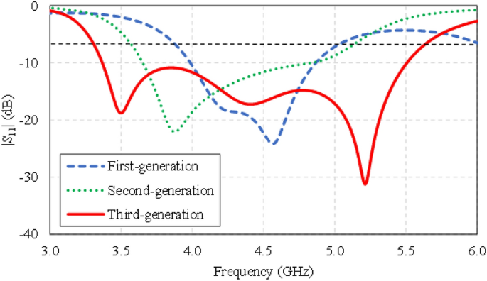
The evolution of the single-element antenna involves three steps: first-, second-, and third-generation antennas, as shown Fig. 3a–c. The first-generation antenna is of dual-arm antenna structure with a rectangular feeding patch separated by a coupling gap. The simulation results demonstrate that the first-generation antenna fails to cover the entire operating frequency band (i.e., 3.5–5.5 GHz). Specifically, the first-generation antenna suffers from a narrow impedance bandwidth, covering 3.8–5.0 GHz.
In the second-generation antenna, the rectangular feeding patch is transformed into a T-shaped feeding patch to improve the impedance bandwidth. In addition, the length of the coupling gap is extended. However, the second-generation antenna still fails to cover the entire operating frequency band, covering 3.4–5.0 GHz.
In the third-generation antenna, the T-shaped feeding patch is reshaped into a hemispherical T-shaped feeding patch, and the ground plane is reconfigured into conjoined triangles (i.e., defected ground plane). The third-generation antenna covers the entire operating frequency band, covering 3.4–5.6 GHz.
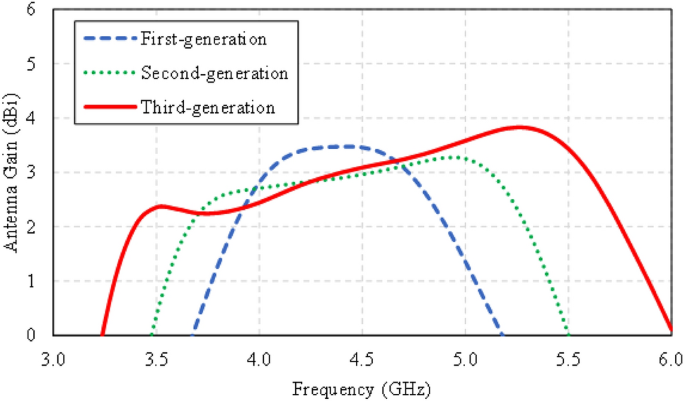
Figure 4 compares the simulated impedance bandwidths (|S11|≤ − 6 dB) of the first-, second-, and third-generation single-element antennas. The first- and second-generation antennas have a narrow impedance bandwidth, covering 3.8–5.0 GHz and 3.4–5.0 GHz, respectively. The third-generation antenna achieves a wider impedance bandwidth, covering 3.4–5.6 GHz. Figure 5 shows the simulated antenna gains of the first-, second-, and third-generation single-element antennas.
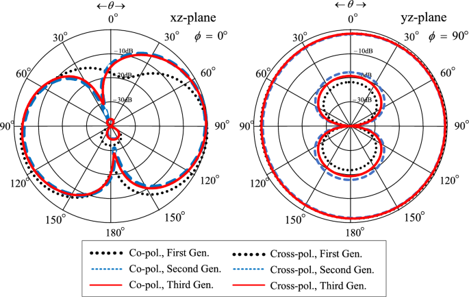
Figure 6 shows the simulated xz- and yz-plane radiation patterns of the first-, second-, and third-generation single-element antennas. Although the radiation patterns of the three antennas closely resemble one another, only the third-generation antenna can cover the entire operating frequency band (3.5–5.5 GHz). As a result, the third-generation single-element antenna is selected for subsequent experiment.
Figure 7 illustrates the equivalent circuit model of the third-generation single-element antenna to determine the impedance matching and bandwidth across the operating frequency band. The equivalent circuit model consists of a series RLC, three parallel RLC circuits, and a series LC component. The initial values of the equivalent circuit elements are calculated by43, and the optimized component values are determined by using ADS software.
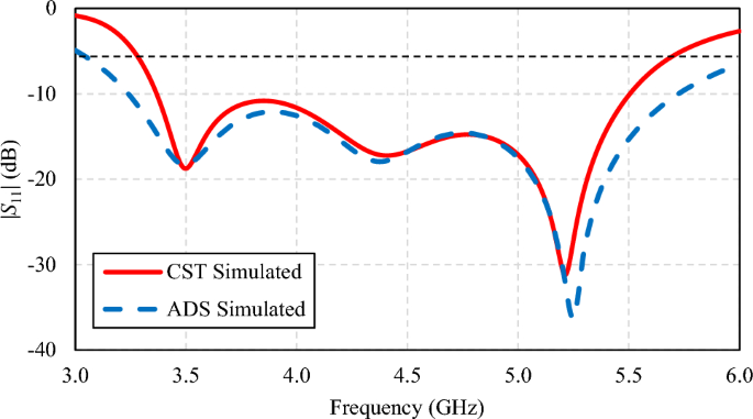
Figure 8 compares the simulated impedance bandwidths (|S11|≤ − 6 dB) of the third-generation single-element antenna by CST and by ADS. In the figure, the first, second, and third parallel RLC circuits resonate at 3.5, 4.4, and 5.25 GHz, respectively, corresponding to the surface current distribution in Figs. 9 and 10. Both CST and ADS models achieve wide impedance bandwidth across the operating frequency band of 3.5 to 5.5 GHz.
Surface Current Distribution of Twin-Element MIMO Antenna Scheme
The surface current distribution of the twin-element MIMO antenna scheme is simulated by exciting one element and terminating the other element using a 50 Ω load. The twin-element MIMO antenna scheme comprises two elements of the third-generation antenna due to the wide impedance bandwidth and high gain characteristics (Figs. 4 and 5).
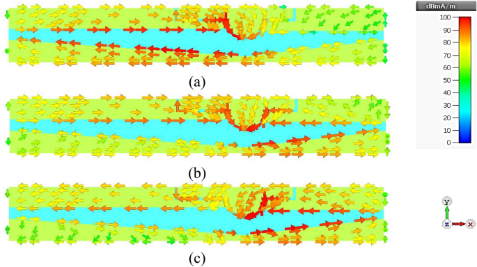
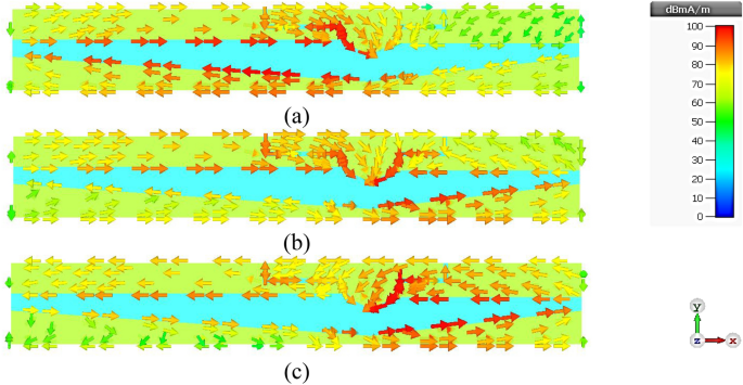
Figure 9a–c show the surface current distribution of the twin-element MIMO antenna scheme at 3.5, 4.5, and 5.5 GHz, with the 1st antenna element excited and the 2nd antenna element terminated. At 3.5 GHz, the surface current flows along the left-shoulder of the feeding patch, the left-arm radiating patch, and the larger triangular ground plane. At 5.5 GHz, the surface current flows along the right-shoulder of the feeding patch, the right-arm radiating patch, and the smaller triangular ground plane. Specifically, the left-arm radiating patch resonates at the lower frequency of 3.5 GHz, while the right-arm radiating patch resonates at the higher frequency of 5.5 GHz. At 4.5 GHz, the surface current is concentrated around the head of the feeding patch. Given the perfect symmetry of the twin-element antenna scheme, the same behavior is observed when the 1st antenna element is terminated while the 2nd antenna element is excited, as shown in Fig. 10a–c. The mutual coupling (|S12|) between the two antenna elements is less than − 40 dB with negligible current leakage.
Parametric Study of Twin-Element MIMO Antenna Scheme
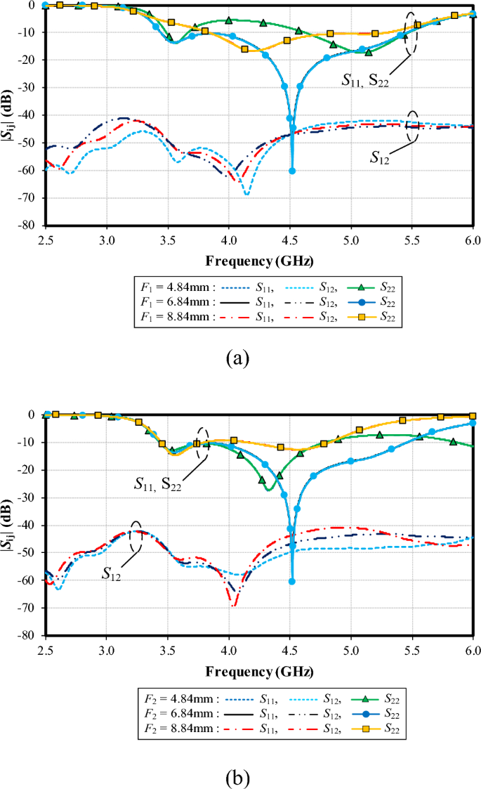
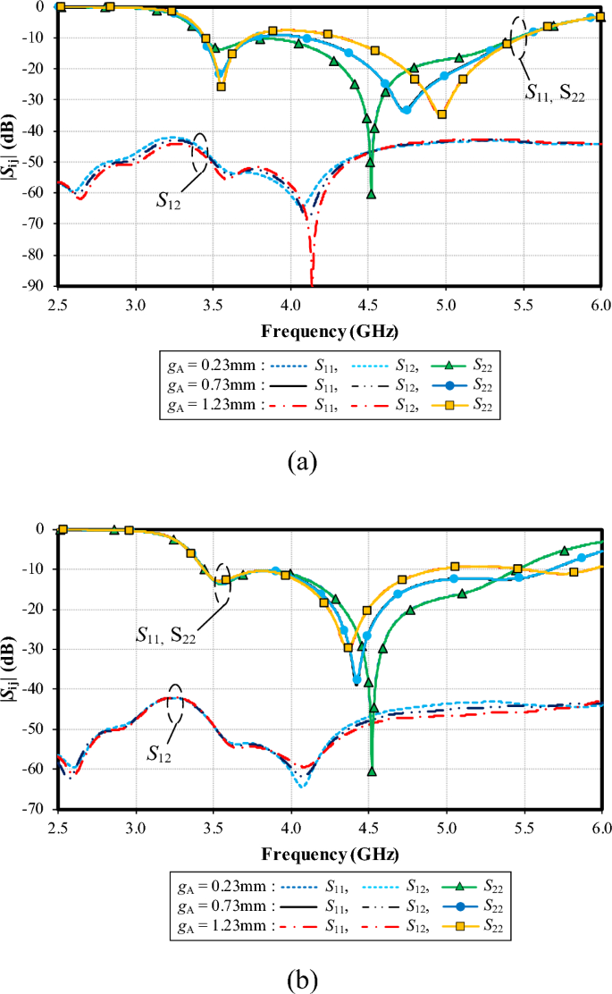
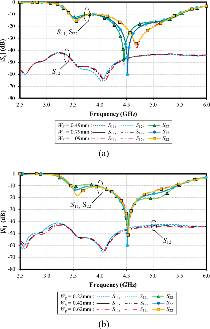
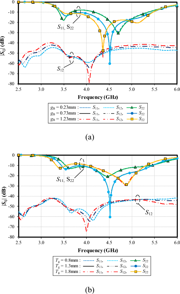
This section examines the effects of antenna parameters on the impedance bandwidth (|S11|, |S22|≤ − 6 dB) and mutual coupling (|S12|) of the proposed twin-element MIMO antenna scheme, as shown in Figs. 11, 12, 13, 14, 15, 16, 17 and 19, 20.
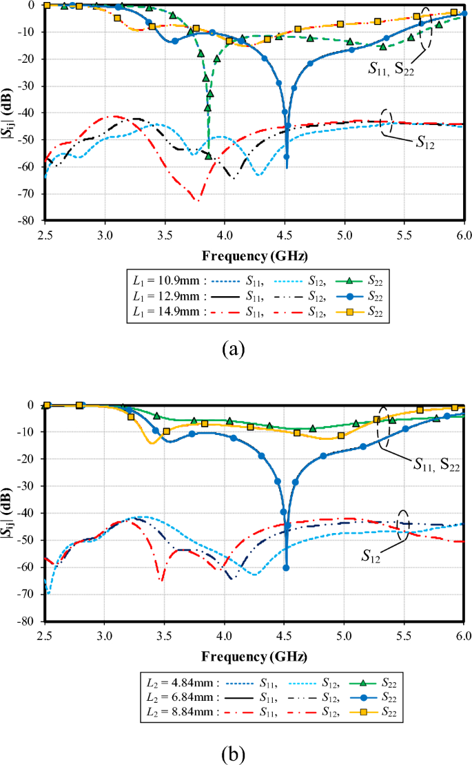
Figure 11a shows the simulated impedance bandwidth (|S11|, |S22|≤ − 6 dB) and mutual coupling (|S12|) under variable L1: 10.9, 12.9, and 14.9 mm. With L1 = 10.9 mm, the resonance frequency is at 3.8 GHz, with the impedance matching of − 54 dB. With L1 = 12.9 mm, the resonance frequency is at 4.5 GHz (− 60 dB). Given L1 = 14.9 mm, the resonance frequency is at 4.25 GHz (− 15 dB). The optimal L1 is thus 12.9 mm. The mutual coupling (|S12|) is less than − 40 dB for the entire operating frequency band, independent of L1.
Figure 11b shows the simulated |S11|, |S22| and |S12| under variable L2: 4.84, 6.84, and 8.84 mm. Given L2 = 6.84 mm, the lowest impedance matching of − 60 dB is achieved at 4.5 GHz (i.e., the resonance frequency). The optimal L2 is 6.84 mm. The mutual coupling (|S12|) is less than − 40 dB for the entire operating frequency band, independent of L2.
Figure 12a shows the simulated |S11|, |S22| and |S12| under variable lengths of the left shoulder of the feeding patch (F1): 1.87, 3.87, and 5.87 mm. Given F1 = 3.87 mm, the lowest impedance matching of − 60 dB is achieved at 4.5 GHz. |S12| is below − 40 dB for the entire operating frequency band, independent of F1.
Figure 12b shows the simulated |S11|, |S22| and |S12| under variable lengths of the right shoulder of the feeding patch (F2): 0.32, 2.32, and 4.32 mm. With F2 = 0.32 mm, the resonance frequency is at 4.3 GHz, with the impedance matching of − 28 dB. With F2 = 2.32 mm, the resonance frequency is at 4.5 GHz (− 60 dB). With F2 = 4.32 mm, the resonance frequency is at 3.6 GHz (− 15 dB). The optimal F2 is 2.32 mm. |S12| is less than − 40 dB for the entire operating frequency band, independent of F2.
Figure 13a, b show the simulated |S11|, |S22| and |S12| of the left and right shoulders of the feeding patch under variable widths of coupling gap (gA): 0.23, 0.73, and 1.23 mm. In Fig. 11a (for the left shoulder of the feeding patch), with gA = 0.23 mm, the resonance frequency is at 4.5 GHz, with the impedance matching of − 60 dB. With gA = 0.73 mm, the resonance frequency is at 4.75 GHz (− 32 dB) and at 5 GHz (− 35 dB) for gA = 1.23 mm.
In Fig. 13b (for the right shoulder of the feeding patch), with gA = 0.23 mm, the resonance frequency is at 4.5 GHz, with the impedance matching of − 60 dB. With gA = 0.73 mm, the resonance frequency is at 4.4 GHz (− 40 dB) and at 4.35 GHz (− 30 dB) for gA = 1.23 mm. The optimal gA is thus 0.23 mm, achieving the lowest impedance matching (− 60 dB) at the center frequency of 4.5 GHz for the left and right shoulders of the feeding patch.
Figure 14a shows the simulated |S11|, |S22| and |S12| under variable width of the T-shaped shoulder (Wf): 0.49, 0.79, and 1.09 mm. With Wf = 0.49 mm, the resonance frequency is at 4.45 GHz, with the impedance matching of − 50 dB, and the resonance frequency is at 4.5 GHz (− 60 dB) for Wf = 0.79 mm. Given Wf = 1.09 mm, the resonance frequency is at 4.65 GHz (− 38 dB). The optimal Wf is 0.79 mm. The mutual coupling (|S12|) is below − 40 dB for the entire operating frequency band, independent of Wf.
Figure 14b shows the simulated |S11|, |S22| and |S12| under variable width of the expanded width of ground plane (Wg): 0.22, 0.42, and 0.62 mm. The resonance frequency is almost identical (at 4.5 GHz), independent of Wg. However, the lowest impedance matching of − 60 dB is achieved with Wg = 0.42. Therefore, the optimal Wg is 0.42.
Figure 15a shows the simulated |S11|, |S22| and |S12| under variable width between the feeding patch and ground plane (gB): 1.01, 1.51, and 2.01 mm. With gB = 1.01 mm, the resonance frequency is at 4.7 GHz, with the impedance matching of − 30 dB, and the resonance frequency is at 4.5 GHz (− 60 dB) for gB = 1.51 mm. Given gB = 2.01 mm, the resonance frequency is at 4.3 GHz (− 50 dB). The optimal gB is 1.51 mm. The mutual coupling (|S12|) is below − 40 dB for the entire operating frequency band, independent of gB.
Figure 15b shows the simulated |S11|, |S22| and |S12| under variable height of the base of small- (right) and large-triangle (left) ground plane (Tg): 0.80,1.30, and 1.80 mm. Given Tg = 1.30 mm, the resonance frequency is at the center frequency of 4.5 GHz, achieving the lowest impedance matching of − 60 dB. The optimal Tg is 1.30 mm. The mutual coupling |S12| is below − 40 dB for the entire operating frequency band, independent of Tg.
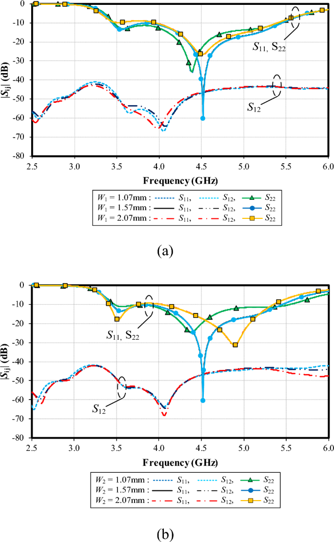
Figure 16a shows the simulated |S11|, |S22| and |S12| under variable width of the left-arm radiating patch (W1): 1.07, 1.57, and 2.07 mm. With W1 = 1.07 mm, the resonance frequency is at 4.4 GHz, with the impedance matching of − 35 dB, and the resonance frequency is at 4.5 GHz (− 60 dB) for W1 = 1.57 mm. Given W1 = 2.07 mm, the resonance frequency is at 4.5 GHz (− 28 dB). The optimal W1 is 1.57 mm. The mutual coupling (|S12|) is below − 40 dB for the entire operating frequency band, independent of W1.
Figure 16b shows the simulated |S11|, |S22| and |S12| under variable width of the right-arm radiating patch (W2): 1.27, 1.77, and 2.27 mm. With W2 = 1.27 mm, the resonance frequency is at 4.35 GHz, with the impedance matching of − 25 dB, and the resonance frequency is at 4.5 GHz (− 60 dB) for W2 = 1.77 mm. Given W2 = 2.27 mm, the resonance frequency is at 4.8 GHz (− 30 dB). The optimal W2 is 1.77 mm. The mutual coupling (|S12|) is less than − 40 dB for the entire operating frequency band, independent of W2.
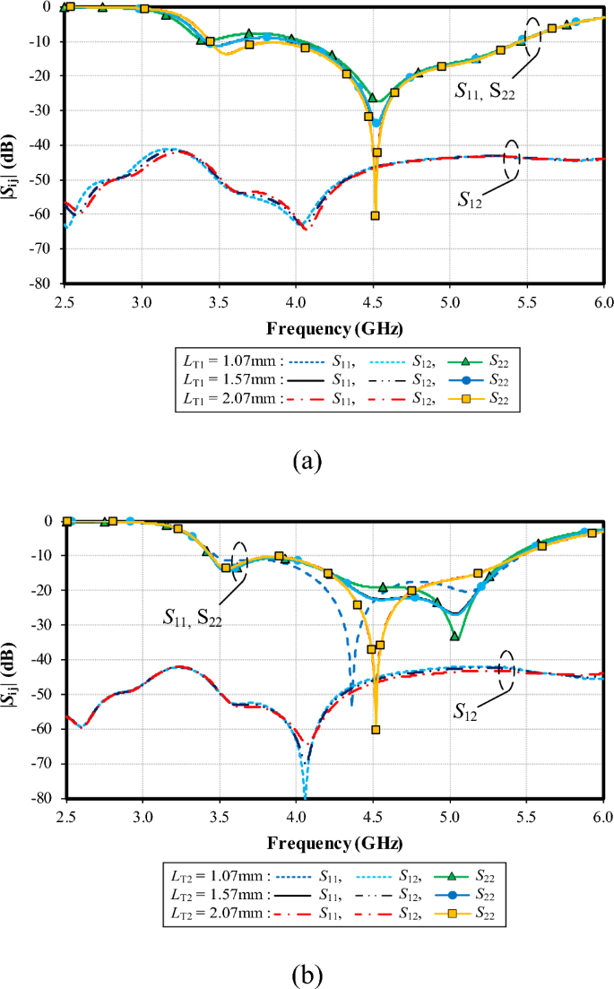
Figure 17a shows the simulated |S11|, |S22| and |S12| under variable length of the larger triangle of the ground plane (LT1): 14.41, 16.41, and 18.41 mm. The resonance frequency is almost identical (at 4.5 GHz), independent of LT1. However, the lowest impedance matching of − 60 dB is achieved with LT1 = 18.41. Therefore, the optimal LT1 is 18.41. The mutual coupling (|S12|) is below − 40 dB for the entire operating frequency band, independent of LT1.
Figure 17b shows the simulated |S11|, |S22| and |S12| under variable length of the smaller triangle of the ground plane (LT2): 6.79, 8.79, and 10.79 mm. With LT2 = 6.79 mm, the resonance frequency is at 5.1 GHz, with the impedance matching of − 32 dB, and the resonance frequency is at 5.1 GHz (− 25 dB) for LT2 = 8.79 mm. Given LT2 = 10.79 mm, the resonance frequency is at 4.5 GHz (− 60 dB). The optimal LT2 is 10.79 mm. The mutual coupling (|S12|) is below − 40 dB for the entire operating frequency band, independent of LT2.
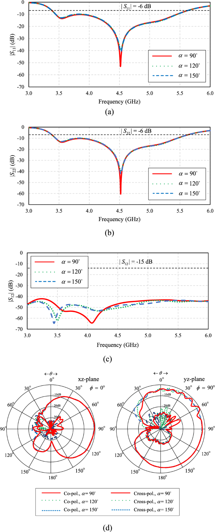
Figure 18a–c depict the laptop model at variable angles (α) of 90°, 120°, and 150°, respectively. Figure 19a–d show the corresponding simulated |S11|, |S22|, |S12|, and radiation pattern of the proposed twin-element MIMO antenna scheme integrated with the laptop model.
In Fig. 19a, b, the simulated |S11| and |S22| are less than − 6 dB across the operating frequency band, independent of α. The results are consistent with43, indicating that the angle (α) of the laptop model has no impact on the impedance bandwidth of the antenna. In Fig. 19c, given α = 90°, the lowest |S12| is closest to the center frequency of 4.5 GHz. In Fig. 19d, the radiation patterns closely resemble one another, independent of α.
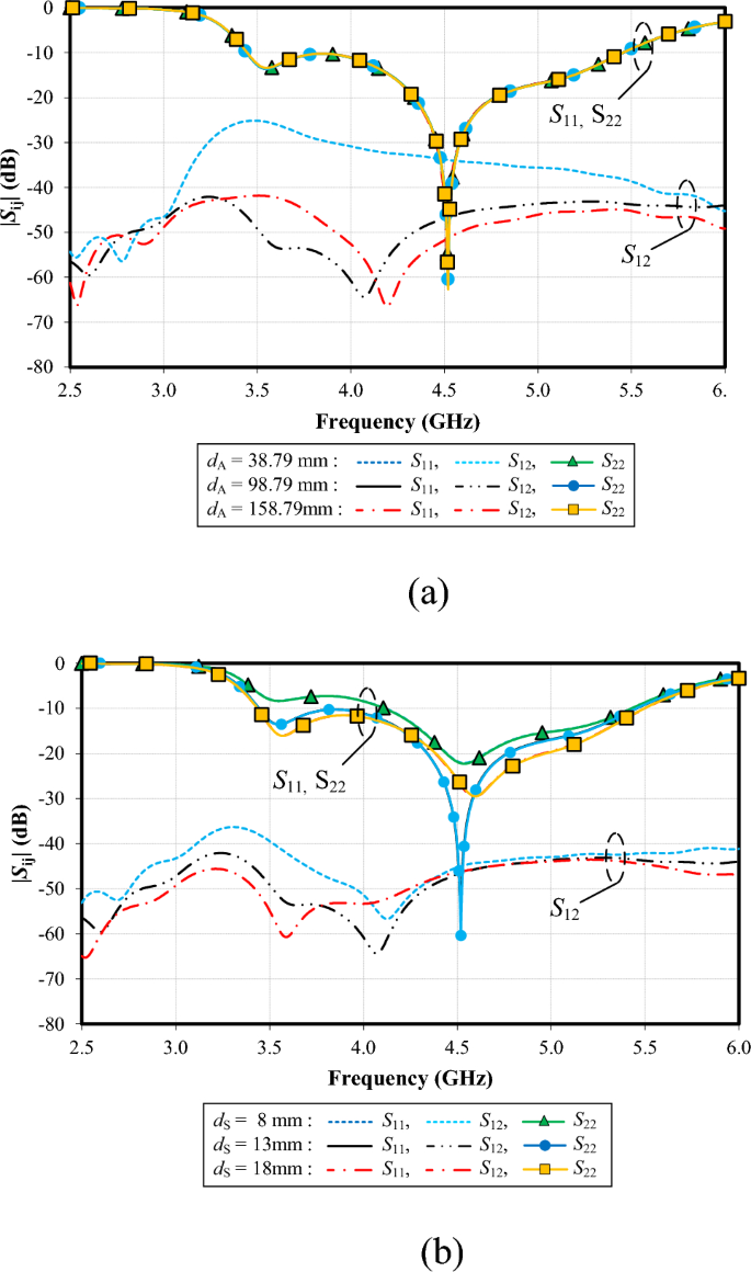
Figure 20a shows the simulated |S11|, |S22| and |S12| under variable edge-to-edge distance between the two antenna elements (dA): 38.79, 98.79, and 158.79 mm. The resonance frequency is almost identical (at 4.5 GHz), independent of dA. The mutual coupling (|S12|) is higher than − 40 dB between 3.1 and 5.5 GHz for dA = 38.79 mm. In contrast, the mutual coupling (|S12|) is below − 40 dB for the entire operating frequency band for dA = 98.79 mm and 158.79 mm. Due to its smaller distance, dA = 98.79 mm is the optimal choice.
Figure 20b shows the simulated |S11|, |S22| and |S12| under variable vertical distance between the reflector and the base of the antenna element (dS): 8, 13, and 18 mm. The resonance frequency is almost identical (at 4.5 GHz), independent of dS. However, the lowest impedance matching of − 60 dB is achieved with dS = 13 mm. Therefore, the optimal dS is 13 mm. The mutual coupling (|S12|) exceeds − 40 dB between 3.1 and 3.5 GHz for dS = 8 mm. With dS = 13 mm and 18 mm, the mutual coupling (|S12|) remains below − 40 dB across the entire frequency band. Given its smaller distance, dS of 13 mm is selected.
Simulated impedance bandwidth (|S11|, |S22|≤ − 6 dB) and mutual coupling (|S12|) of the proposed twin-element MIMO antenna scheme integrated with the laptop model under variable edge-to-edge distance between the two antenna elements (dA) and vertical distance between the reflector and the base of the antenna element (dS): (a) dA, (b) dS.
[ad_2] ->Google Actualités


